Fencing Testbox
Project Overview
Low-cost electrical continuity tester for fencing body cords and blades.
Designed to replace multimeter-based testing with a single-purpose, fast,
field-deployable tool suitable for student clubs and armorers.
Design Requirements
| Requirement | Target | Rationale |
|---|---|---|
| Test body cords | Foil / Sabre / Epee | Cover all competition weapons |
| Test blades | Continuity + isolation | Common failure modes during competition |
| User interface | LED-based pass/fail | Fast diagnosis, no interpretation |
| Cost | < $30 BOM | Accessible to student clubs |
| Portability | Handheld, battery powered | Use at practice and tournaments |
Key Considerations & Trade-offs
- Multimeter vs Dedicated Tester: Multimeters are flexible but slow and error-prone for repetitive testing.
- LED indication vs numeric resistance: LEDs reduce resolution but dramatically improve speed and usability.
- Hand-wired vs PCB: Hand wiring enabled rapid prototyping; PCB improved reliability and assembly.
- Compact enclosure vs assembly access: Early compact designs increased assembly difficulty.
Down-Selection Rationale
- Selected LED-based continuity detection over resistance display for speed and robustness.
- Moved all connectors to a single face to enable PCB integration.
- Chose 3D printed enclosure to allow rapid iteration and low-volume production.
- Finalized on PCB-based design to reduce wiring errors and assembly time.
Build, Testing & Validation
- First Prototype: Cardboard enclosure, hand-wired, validated concept feasibility.
- Second Prototype: First 3D printed housing; revealed assembly and wiring complexity issues.
- Third Prototype: Improved internal layout and battery placement.
- Final Prototype: Custom PCB designed in KiCad and fabricated via PCBWay.
- Validated functionality using known-good and faulty body cords and blades.
- Identified remaining fitment issues suitable for Rev B enclosure changes.
Image Gallery
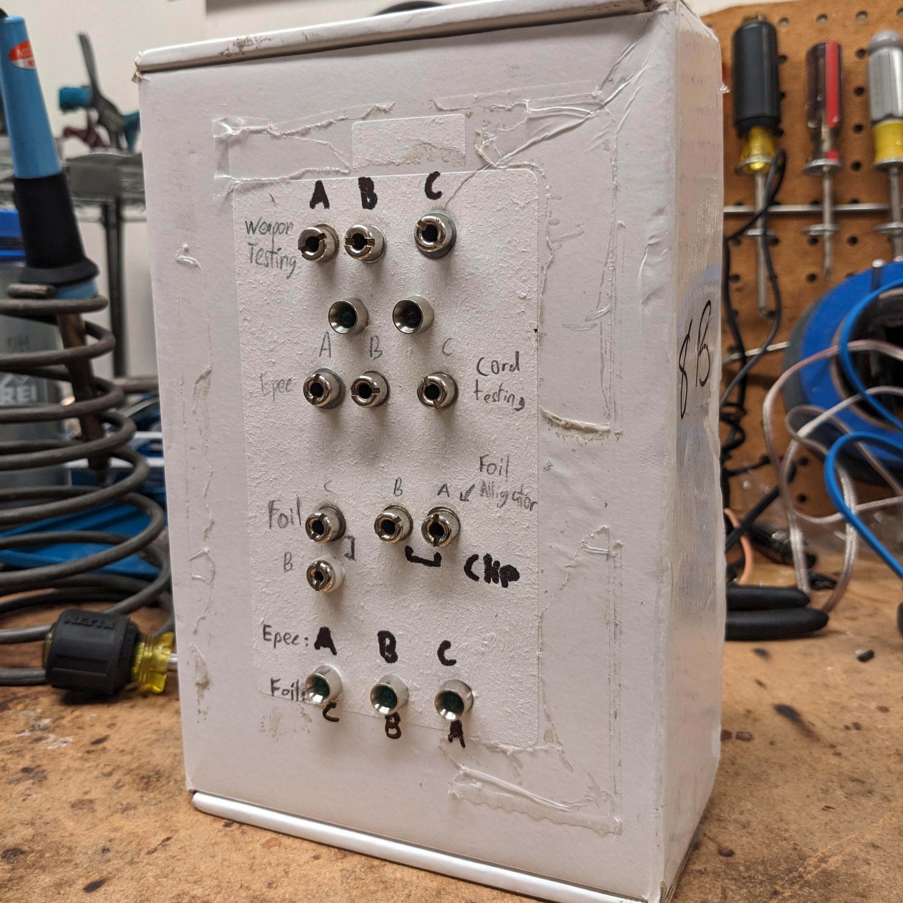 I started out by making a proof of concept in a cardboard box using spare parts from fencing sockets. This was crude, but was already making my work much easier.
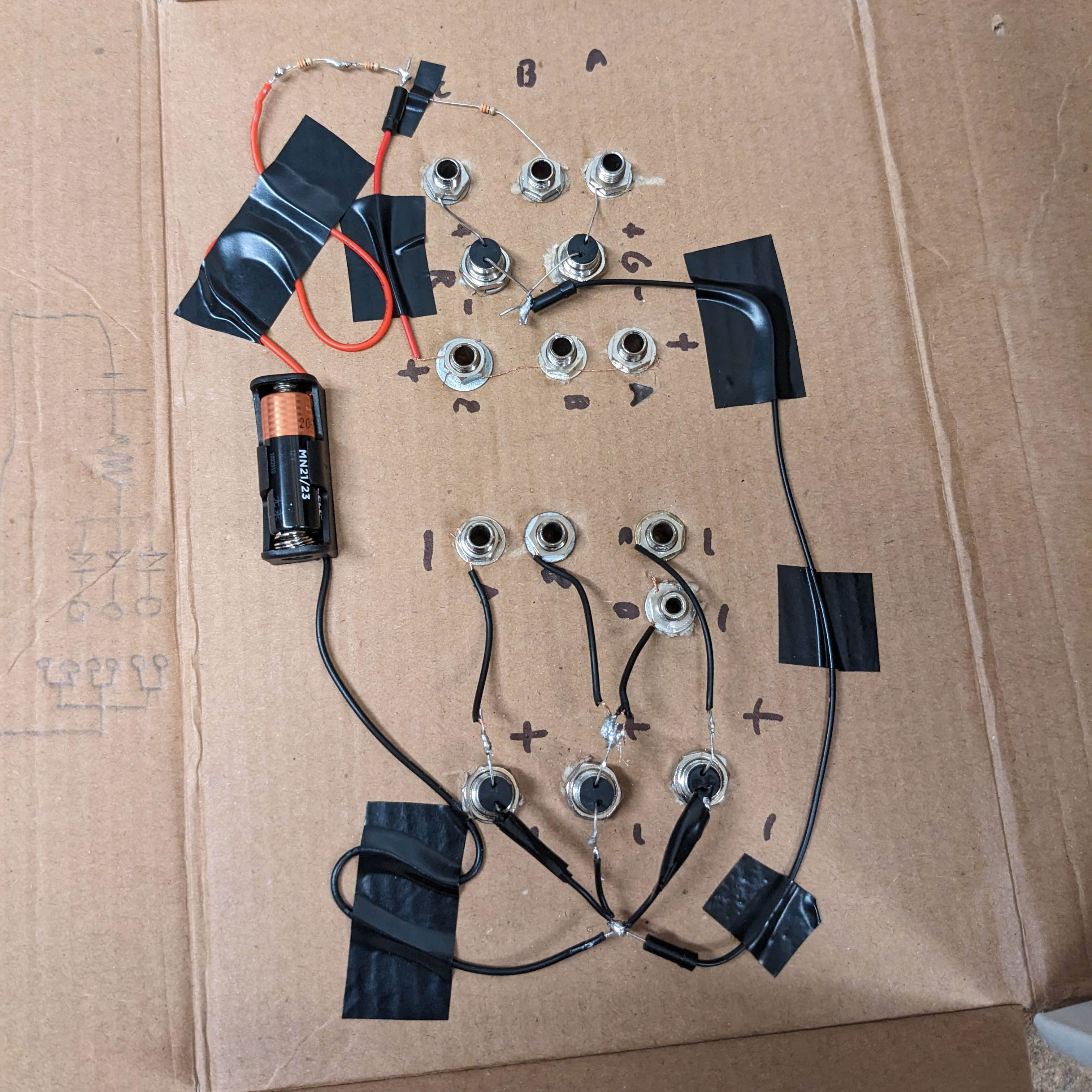 Instead of using a multimeter, an LED indicated an electrical connection. Though this isn't precise, it gets the job done.
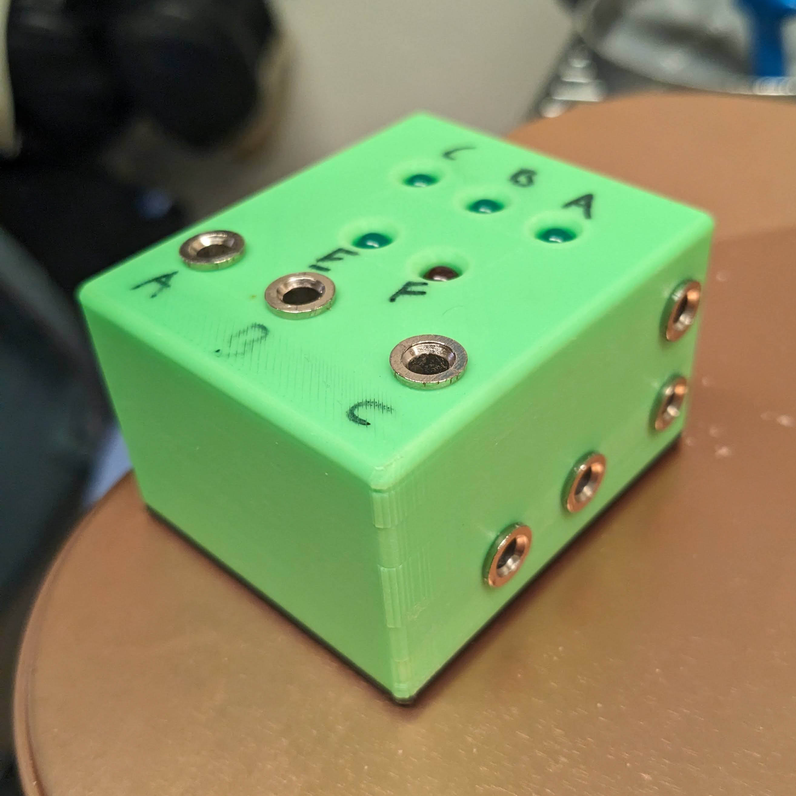 This was my first 3D printed prototype. I experimented with a design that had sockets on three surfaces of the device which made it very compact, but settled on using just
the top surface to facilitate moving over to using a PCB instead of hand soldering every component.
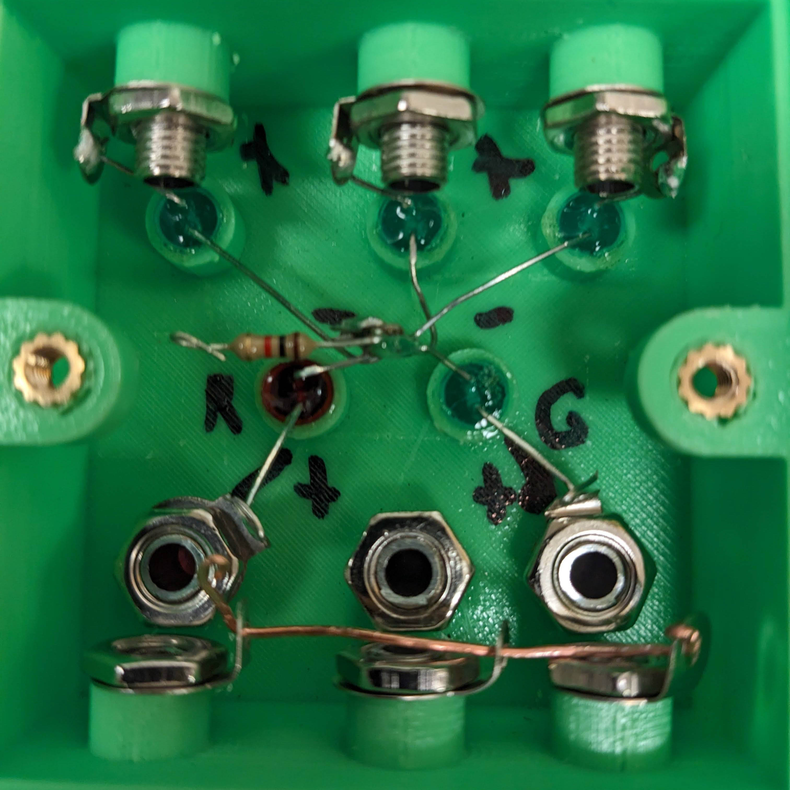 This is the inside of the first 3D printed prototype. One of the issues with making a compact 3D circuit was that assembling it was annoying.
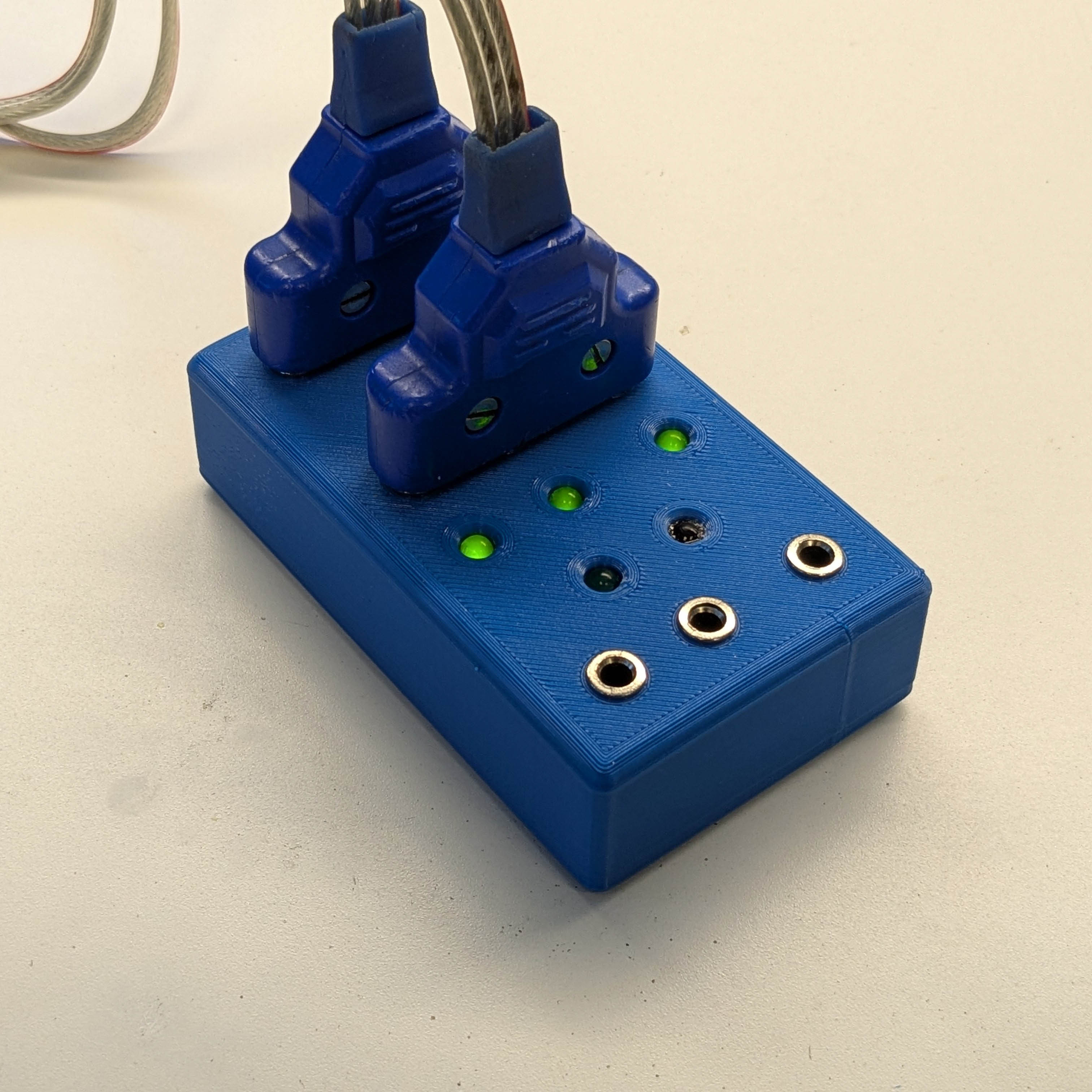 For my second prototype, I simplified the circuit and moved all the electrical connections to the top surface of the device. Shown above is how an epee body cord would be
tested. Because all three LED's are illuminated, that indicates a good body cord. The two unlit LED's and empty sockets at the bottom are for blade testing.
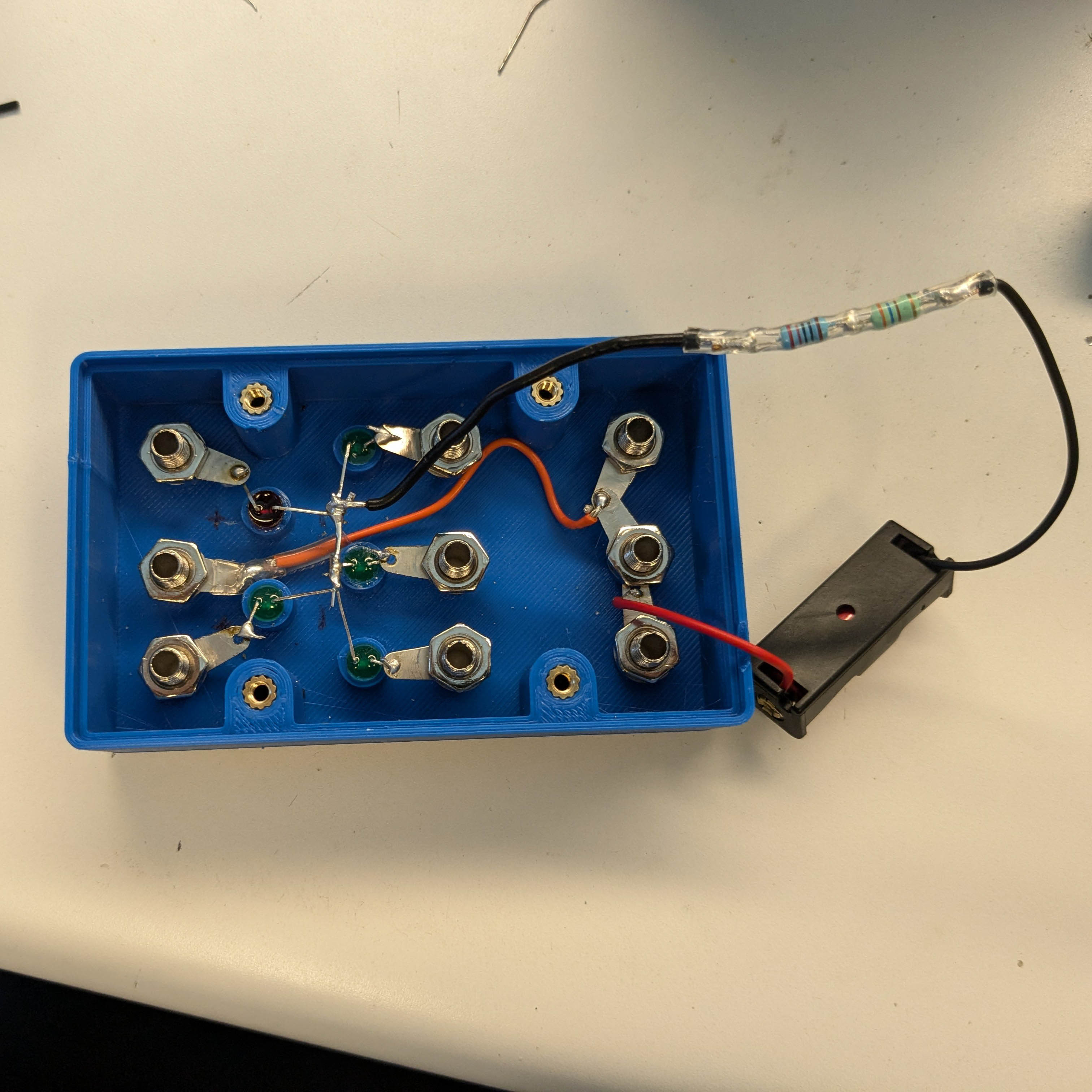 This was the inside of the second prototype. Though this was still hand soldered, assembly was much easier than before. I still needed to resolve battery placement though.
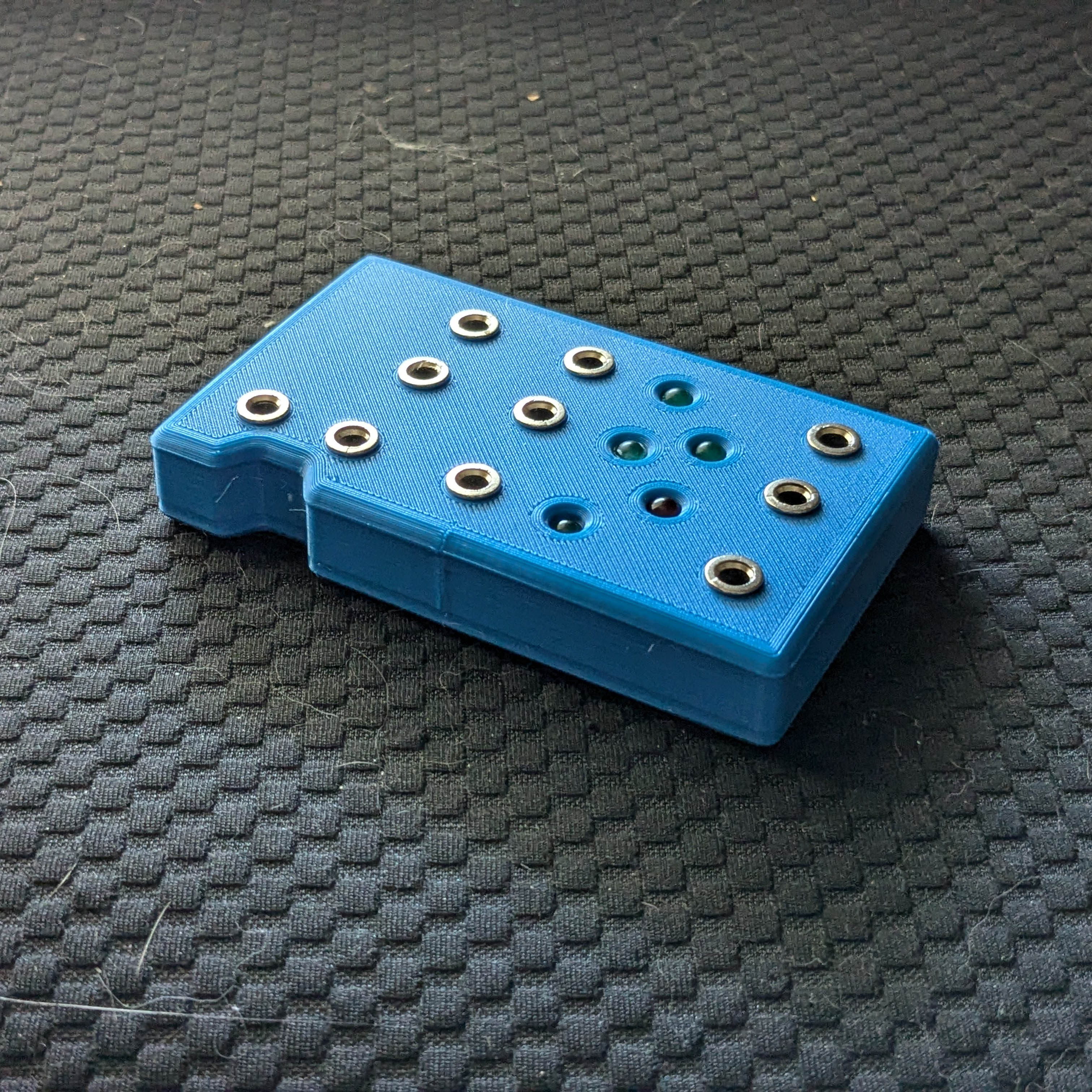 For the third prototype, I modified the housing by adding testing functionality for foil body cords.
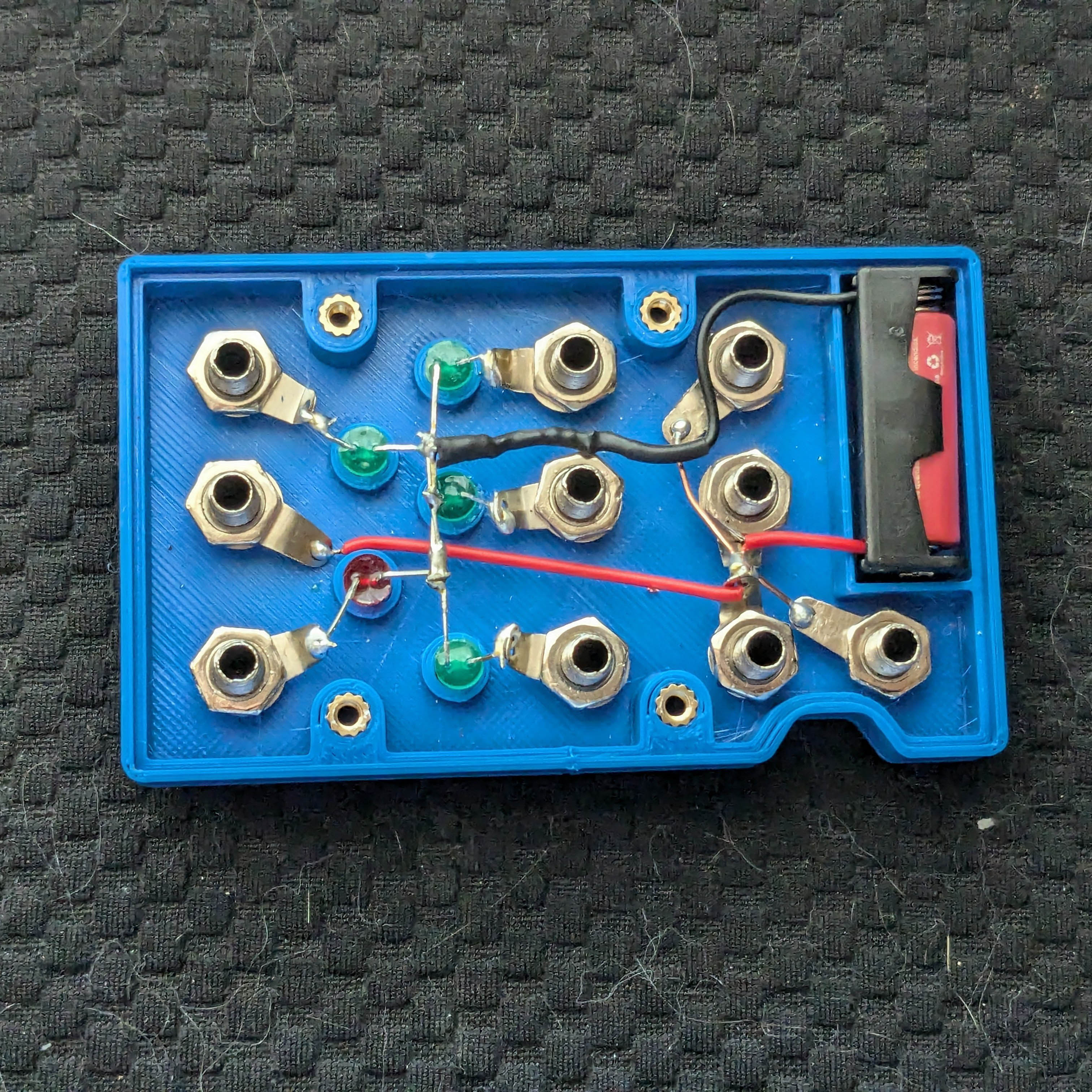 On the inside of the housing of the third prototype, I added a dedicated place for the battery.
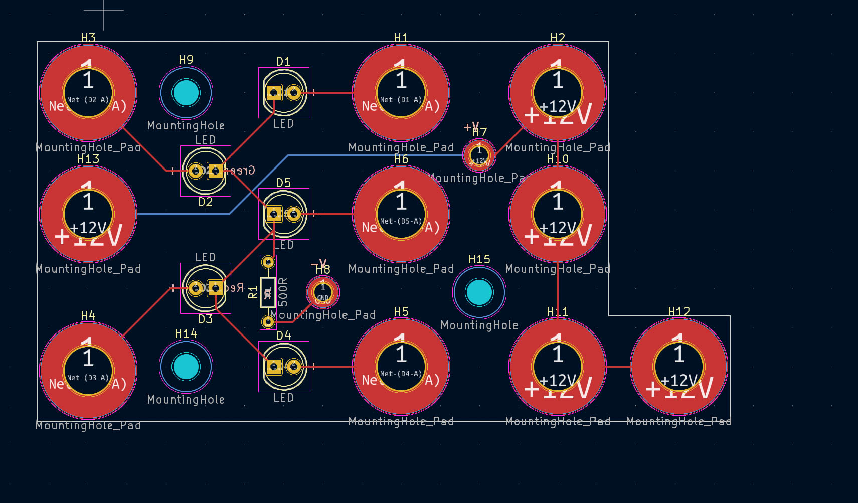 For the fourth and final prototype, I learned how to design and order a custom PCB using KiCad and PCB Way. I used the knowledge I gained from this phase of the project
in future projects as well, such as the Automatic Bicycle Shifter.
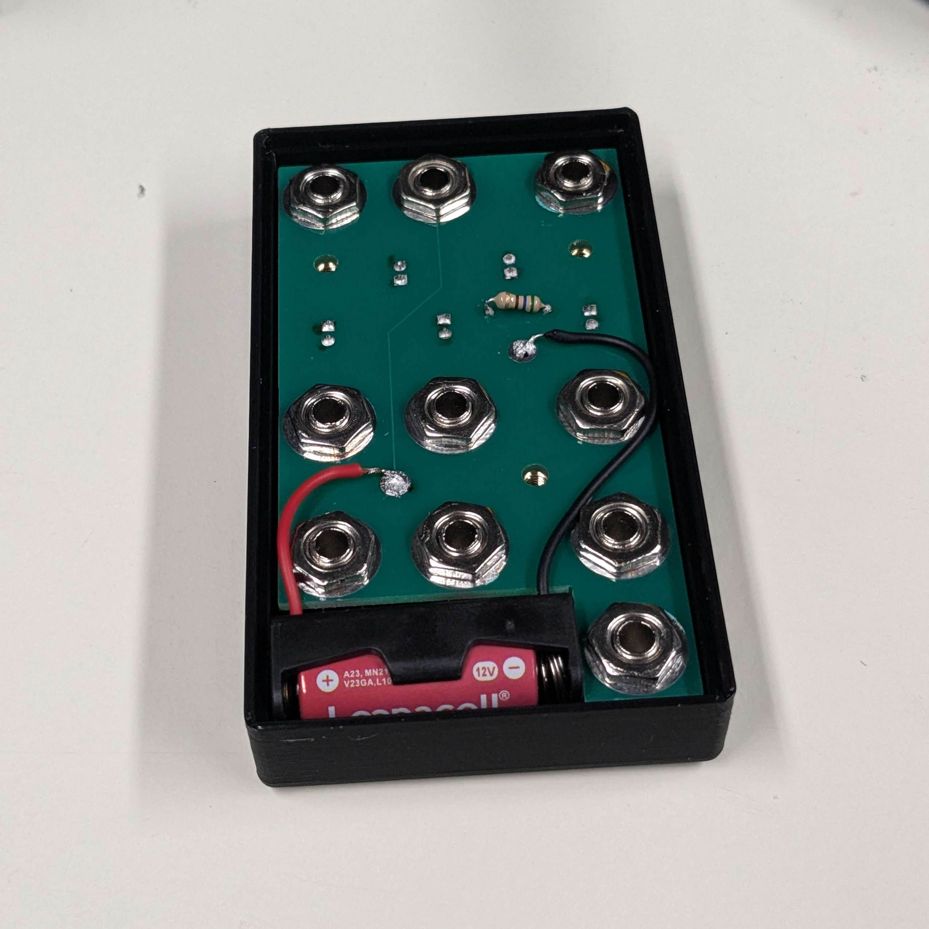 This is the inside of the assembled final tester. Putting this together was a breeze compared to the previous iterations of this product, but it still had some minor
fitment issues.
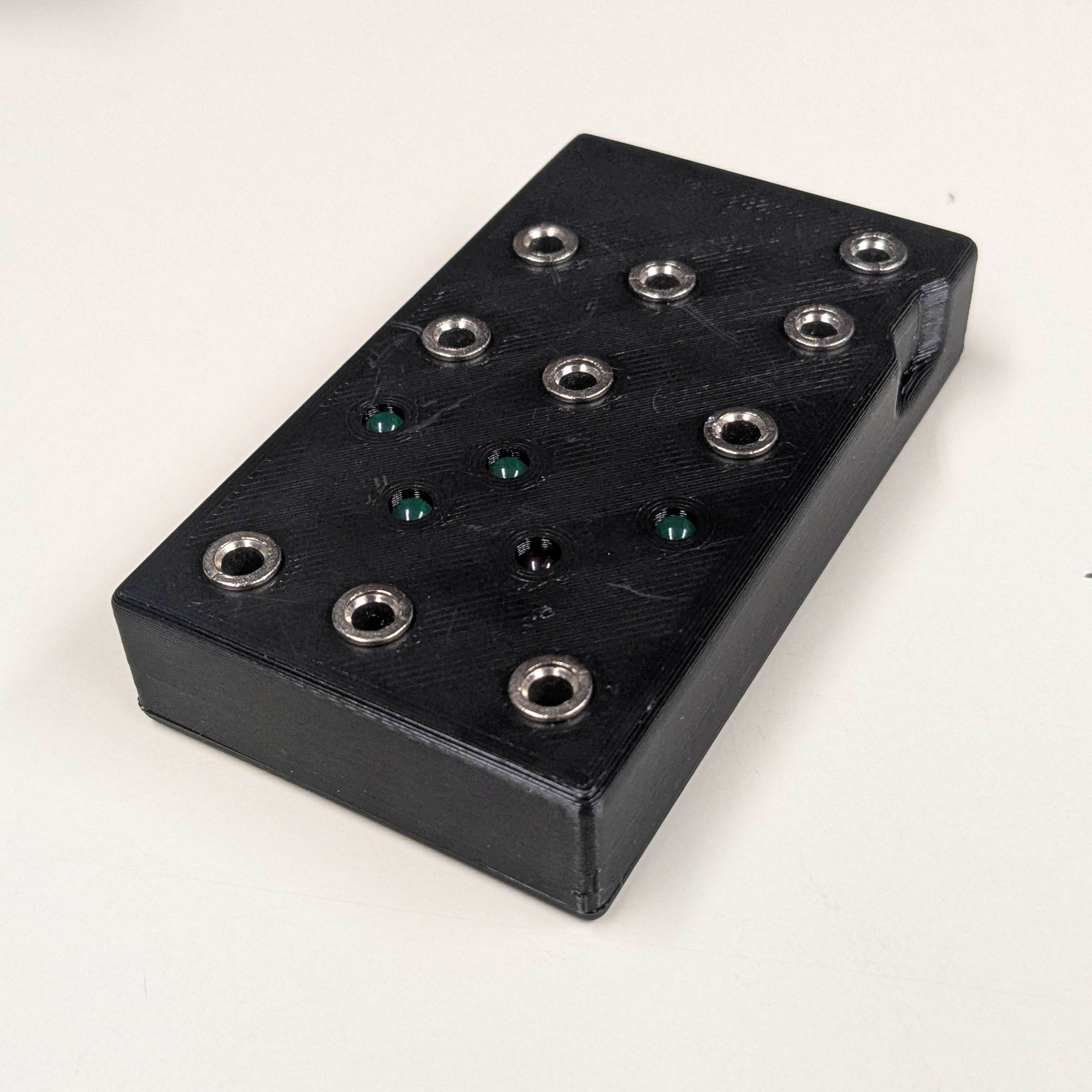 This is the final assembled tester. I can edit this version forever trying to come up with a perfect design, but I think that this is a good stopping point with its current
functionality. For a more advanced tester that can compete with professional equipment, I am looking into incorporating a microprocessor for displaying resistance values of wires being tested, as
well as switching between different modes for different testing scenarios.